 ALLPCB


When designing a printed circuit board (PCB), every detail matters, including the color of the solder mask. But does the solder mask color really affect signal integrity and overall PCB performance, especially in high-frequency designs? The short answer is: not directly. Solder mask color itself does not impact signal integrity or performance. However, the material properties of the solder mask, such as its dielectric constant (Dk) and thickness, can influence factors like signal attenuation and impedance, particularly in high-frequency PCB design. In this blog, we’ll dive deep into the relationship between solder mask properties and PCB performance, exploring key concepts like solder mask dielectric properties and their effects on signal integrity.
What Is a Solder Mask and Why Does It Matter?
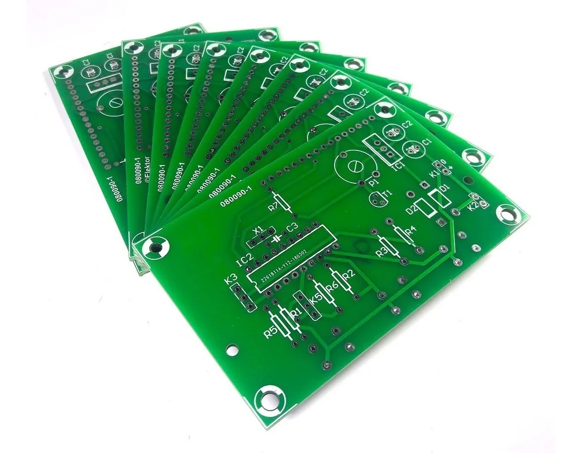
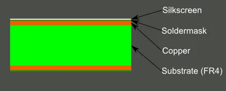
A solder mask is a thin protective layer applied to a PCB to insulate copper traces and prevent solder from bridging between components during assembly. It also shields the board from environmental factors like moisture and dust. While the color of the solder mask—whether green, blue, red, or black—is often chosen for aesthetic or branding reasons, the material composition and application of the mask play a much larger role in the board’s functionality.
In high-frequency PCB design, where signals travel at rapid speeds, even small variations in materials can affect performance. This is where solder mask dielectric properties come into focus. The dielectric constant (Dk) of the solder mask material determines how it interacts with electric fields, which can influence signal speed and integrity. Let’s explore how these properties, rather than color, are critical to understanding PCB performance.
Understanding Solder Mask Dielectric Properties
The dielectric constant (Dk) of a material measures its ability to store electrical energy in an electric field. For solder masks, the Dk typically ranges from 3.0 to 4.5, depending on the specific formulation. A higher Dk means the material can slow down electrical signals more than a material with a lower Dk. In high-frequency PCB design, this can lead to signal attenuation, where the signal loses strength as it travels through the board.
For comparison, the substrate material of a PCB, like FR-4, often has a Dk around 4.3 to 4.5 at 1 MHz. If the solder mask’s Dk is significantly different or inconsistently applied, it can create variations in the effective dielectric constant along the signal path. This mismatch can cause impedance discontinuities, leading to reflections and degraded signal integrity on a PCB.
While the color of the solder mask does not inherently change its Dk, different colors might indicate variations in material composition or thickness due to manufacturing processes. However, these differences are usually minimal and not directly tied to color. Instead, focus on the solder mask’s formulation and application when assessing its impact on performance.
Signal Integrity in PCBs: How Solder Mask Plays a Role
Signal integrity refers to the ability of a signal to maintain its quality as it travels through a PCB. Poor signal integrity can result in data errors, noise, or complete signal failure, especially in high-frequency applications like telecommunications or RF circuits. Several factors influence signal integrity, including trace layout, substrate material, and yes, the solder mask.
In high-frequency PCB design, the solder mask can affect signal integrity in a few key ways:
- Effective Dielectric Constant: The solder mask adds a layer over the copper traces, slightly altering the effective Dk of the signal path. For microstrip traces (traces on the outer layer of a PCB), the solder mask’s Dk can impact signal speed and impedance. For example, a solder mask with a Dk of 4.0 over a trace on an FR-4 substrate (Dk of 4.3) can reduce the effective Dk slightly, affecting signal propagation.
- Signal Attenuation: At high frequencies, signal attenuation becomes a concern. This is the loss of signal strength due to factors like dielectric loss (measured by the dissipation factor, Df) and skin effect. A solder mask with a high Df can contribute to greater signal loss. Typical Df values for solder masks range from 0.02 to 0.03, and selecting a mask with a lower Df can minimize attenuation in high-frequency designs.
- Impedance Control: Impedance mismatches can cause signal reflections, degrading performance. The thickness and uniformity of the solder mask layer can influence characteristic impedance. For a 50-ohm trace, a variation in solder mask thickness from 0.5 mils to 1.5 mils can shift impedance by 1-2 ohms, which might be significant in sensitive designs.
These effects are tied to the solder mask’s material properties, not its color. Whether your PCB has a green, blue, or black solder mask, the impact on signal integrity will depend on the mask’s Dk, Df, and application consistency.
High-Frequency PCB Design: Challenges and Solder Mask Considerations
High-frequency PCB design, often used in applications like 5G, radar, and high-speed digital circuits, demands precise control over every aspect of the board. Frequencies above 1 GHz amplify the impact of small variations in material properties, making the solder mask’s role more critical.
Here are some specific challenges in high-frequency designs related to solder mask:
- Signal Speed Variations: At high frequencies, the signal speed is inversely related to the square root of the effective dielectric constant. If a solder mask increases the effective Dk by even 0.1, signal speed can decrease, potentially causing timing issues in synchronized systems.
- Return Loss and Insertion Loss: Research shows that solder mask can contribute to return loss (signal reflection) and insertion loss (signal power loss). For instance, a study on high-speed PCBs found that a thicker solder mask layer (around 1.2 mils) increased insertion loss by 0.2 dB at 10 GHz compared to a thinner layer (0.5 mils).
- Trace Coverage: In some high-frequency designs, engineers opt to leave certain traces uncovered by solder mask to minimize its impact on impedance and loss. This approach requires careful planning to avoid exposing traces to environmental damage.
For high-frequency applications, selecting a solder mask with a low Dk and low Df is often more important than worrying about its color. Many manufacturers offer specialized solder mask materials designed for high-frequency use, with Dk values closer to 3.0 and Df values below 0.02.
Does Solder Mask Color Indicate Performance Differences?
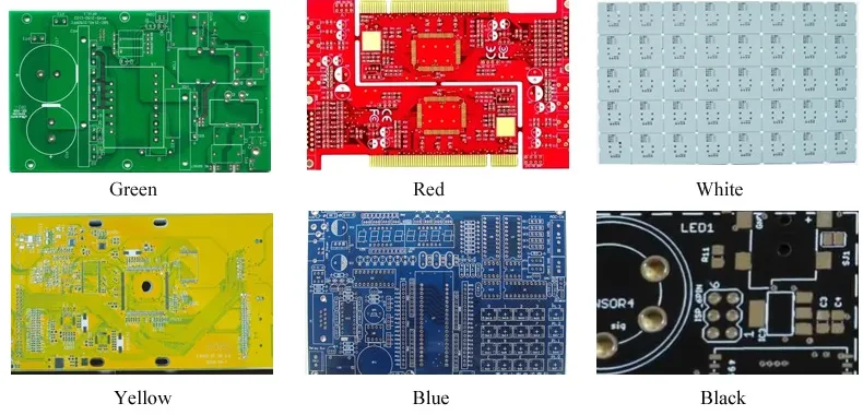
One common misconception is that solder mask color correlates with performance. While it’s true that different colors might be associated with specific formulations or brands of solder mask, there’s no universal standard linking color to dielectric properties or signal integrity. For example, green solder mask, the industry standard, is often chosen for its high contrast and visibility during inspection. Black solder mask might be used for aesthetic reasons or to reduce light reflection in optical devices. However, the color pigment itself has negligible impact on electrical performance.
That said, if a manufacturer uses different materials or processes for different colors, there could be slight variations in Dk or thickness. Always consult the material datasheet or speak with your PCB fabricator to confirm the properties of the solder mask being used, regardless of its color.
How to Optimize Solder Mask for Signal Integrity
While color doesn’t directly affect PCB performance, there are several steps you can take to ensure the solder mask supports signal integrity, especially in high-frequency PCB design:
- Choose the Right Material: Select a solder mask with a low Dk and Df for high-frequency applications. Look for materials specifically rated for RF or high-speed digital circuits.
- Control Thickness: Work with your fabricator to maintain consistent solder mask thickness, typically between 0.5 and 1.0 mils, to avoid impedance variations. Thicker masks can increase dielectric effects, while thinner masks may not provide adequate protection.
- Consider Exposed Traces: For critical high-frequency traces, consider designs that leave traces uncovered by solder mask to eliminate its influence. Use protective coatings or other methods to safeguard exposed areas.
- Simulate and Test: Use simulation tools to model the impact of solder mask on signal integrity before fabrication. Tools can predict impedance, signal attenuation, and other parameters based on material properties and layer stack-up.
- Collaborate with Fabricators: Communicate your performance requirements to your PCB manufacturer. They can recommend suitable solder mask materials and application techniques to meet your needs.
By focusing on these factors, you can minimize the solder mask’s impact on signal integrity and ensure optimal PCB performance, regardless of the color chosen.
Other Factors Affecting Signal Integrity in PCBs
While solder mask dielectric properties play a role in signal integrity, they are just one piece of the puzzle. Other factors can have a more significant impact on performance, especially in high-frequency designs:
- Substrate Material: The PCB substrate, such as FR-4, Rogers, or polyimide, has a much larger influence on signal speed and loss due to its thickness and dielectric properties. For instance, Rogers materials often have a Dk below 3.0, making them ideal for high-frequency applications.
- Trace Geometry: The width, spacing, and length of traces directly affect impedance and crosstalk. A poorly designed trace can cause more signal degradation than any solder mask issue.
- Layer Stack-Up: The arrangement of layers in a multilayer PCB influences signal paths and interference. Proper stack-up design is critical for maintaining signal integrity.
- Environmental Factors: Temperature, humidity, and other conditions can alter material properties over time, affecting performance. Choose materials with stable characteristics under expected operating conditions.
Addressing these elements alongside solder mask considerations will give you a more comprehensive approach to optimizing PCB performance.
Conclusion: Focus on Material, Not Color
In the debate over solder mask color and signal integrity, the evidence is clear: color itself does not affect PCB performance. Instead, the dielectric properties of the solder mask, such as its Dk and Df, along with its thickness and application, are what matter most. For high-frequency PCB design, where signal attenuation and impedance control are critical, selecting the right solder mask material and working closely with your fabricator can make a significant difference.
Whether you choose a green, blue, or black solder mask, prioritize understanding its material specifications and how they align with your design requirements. By focusing on solder mask dielectric properties and other key design factors, you can ensure excellent signal integrity and reliable PCB performance for any application.


