ALLPCB


In the world of printed circuit board (PCB) design, choosing the right assembly method can make or break your project. If you’re wondering whether to use Surface Mount Technology (SMT) or Through-Hole Technology (THT), or even better, how to combine them, you’re in the right place. Hybrid PCB design, which involves a through-hole SMT mix, offers a powerful solution by blending the strengths of both techniques. This approach—combining through-hole and SMT—can optimize performance, durability, and cost for a wide range of applications.
In this comprehensive guide, we’ll dive deep into the benefits of hybrid PCB designs. You’ll learn why integrating THT and SMT components can be a game-changer for your projects, how to apply this approach effectively, and what to consider during the design and assembly process. Whether you’re an electronics engineer or a product developer, this post will provide actionable insights to help you make informed decisions for your next PCB project.
What Is Hybrid PCB Design?
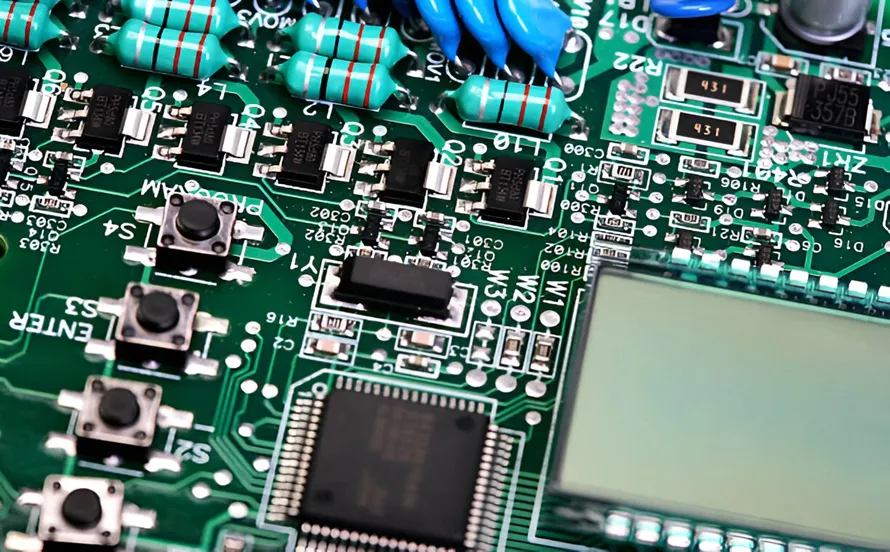
Hybrid PCB design refers to the practice of combining through-hole and SMT components on a single board. SMT involves mounting components directly onto the surface of the PCB, allowing for smaller, lighter, and more densely packed designs. On the other hand, THT involves inserting component leads through drilled holes in the board and soldering them on the opposite side, offering greater mechanical strength and reliability.
By integrating both methods, hybrid PCB design leverages the compactness and efficiency of SMT with the robustness and ease of repair associated with THT. This through-hole SMT mix is especially useful in applications where certain components need high durability (like connectors or power components) while others require a smaller footprint (like microcontrollers or resistors).
Why Choose a Through-Hole SMT Mix? Key Benefits of Hybrid PCB Designs
Combining through-hole and SMT in hybrid PCB designs offers several advantages that make it a preferred choice for many engineers. Below, we explore the key benefits in detail to help you understand why this approach might be the best fit for your project.
1. Enhanced Durability and Reliability
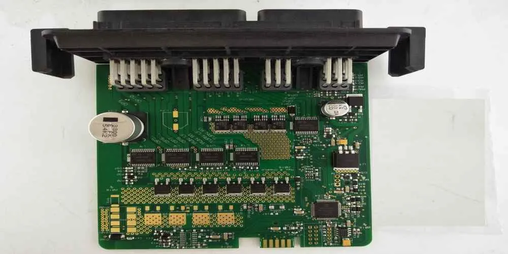
One of the primary benefits of THT components in a hybrid PCB design is their mechanical strength. Components like connectors, transformers, and large capacitors often experience physical stress or vibration during operation. Mounting these through holes ensures a stronger bond to the board, reducing the risk of failure. For example, in automotive or industrial applications, where PCBs may face harsh conditions, THT components can withstand vibrations better than SMT parts, which rely on surface adhesion.
By using THT for critical, high-stress components and SMT for smaller, less mechanically demanding parts, hybrid designs balance reliability with space efficiency. This combination can significantly extend the lifespan of a PCB in rugged environments.
2. Space Efficiency and High-Density Designs
SMT shines when it comes to saving space. Surface-mounted components are smaller and can be placed on both sides of a PCB, allowing for higher component density. This is crucial for modern electronics, where devices are becoming increasingly compact. For instance, a smartphone PCB might use SMT for microchips and resistors to fit everything into a tiny space.
In a hybrid PCB, you can reserve SMT for high-density areas while using THT for larger or high-power components. This through-hole SMT mix maximizes board real estate, enabling complex designs without sacrificing the structural integrity of key components.
3. Cost-Effective Manufacturing and Assembly
While SMT is often associated with lower assembly costs due to automation, THT can be more cost-effective for certain components that require manual insertion or specific soldering techniques. Hybrid PCB designs allow you to optimize costs by selecting the most economical method for each component type. For example, SMT can reduce labor costs for small, repetitive components, while THT may be cheaper for low-volume, high-power parts that don’t justify automated setup.
Additionally, hybrid designs can reduce the need for multiple boards or complex layouts. By combining through-hole and SMT, you might avoid splitting a design across two separate PCBs, saving on material and manufacturing expenses.
4. Improved Thermal and Power Management
High-power components, such as power transistors or voltage regulators, often generate significant heat. THT components are better suited for these applications because their leads provide a direct path for heat dissipation through the PCB. Moreover, THT parts can be paired with heat sinks more effectively, enhancing thermal management.
In a hybrid PCB design, you can use THT for power-handling components to manage heat better while employing SMT for low-power, high-density circuitry. This combination ensures your board performs reliably under varying thermal conditions. For instance, in a power supply design, THT might be used for a transformer with a thermal dissipation rate of up to 5W, while SMT handles smaller control chips nearby.
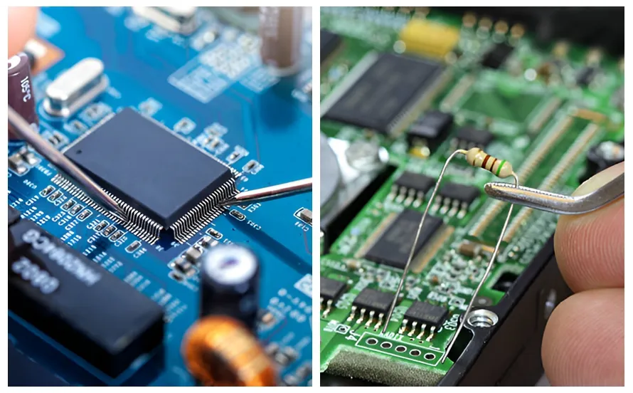
5. Easier Prototyping and Repairs
THT components are easier to work with during prototyping and repairs. Their larger size and accessible leads make manual soldering straightforward, which is ideal for testing and debugging early-stage designs. If a component fails, replacing a THT part is often simpler than desoldering an SMT component, especially for hobbyists or small-scale projects.
In hybrid designs, you can strategically use THT for components likely to need replacement or adjustment, while SMT handles the bulk of the circuitry. This approach simplifies maintenance without compromising on modern design needs.
Applications of Hybrid PCB Designs
The through-hole SMT mix is versatile and suits a wide range of industries and applications. Here are some common scenarios where hybrid PCB designs excel:
- Automotive Electronics: Hybrid PCBs are ideal for automotive systems, where durability (THT for connectors and sensors) and compactness (SMT for control units) are both critical. These boards can handle vibrations and temperature swings while fitting into tight spaces.
- Industrial Equipment: Machinery control systems often require robust power components (THT) alongside dense logic circuits (SMT). Hybrid designs ensure reliability in harsh factory environments.
- Consumer Electronics: Devices like audio amplifiers may use THT for large capacitors and connectors to handle high currents, while SMT manages smaller digital components for user interfaces.
- Medical Devices: Hybrid PCBs balance precision (SMT for microcontrollers) with reliability (THT for critical connectors), ensuring patient safety and device performance.
Best Practices for Combining Through-Hole and SMT in Hybrid PCB Designs
While the benefits of hybrid PCB design are clear, achieving optimal results requires careful planning. Here are some best practices for integrating THT and SMT components effectively:
1. Plan Component Placement Strategically
Group SMT components together to streamline automated assembly processes like pick-and-place machines. Place THT components in areas where manual soldering or wave soldering can be applied without interfering with SMT zones. For example, keep THT connectors near board edges for easy access, while clustering SMT chips in the center for efficient layout routing.
2. Optimize for Manufacturing Processes
Hybrid assembly often involves multiple steps, such as SMT reflow soldering followed by THT wave soldering. Coordinate with your manufacturing partner to ensure the process order minimizes thermal stress on components. For instance, SMT components with lower heat tolerance should be soldered first if possible, followed by THT parts.
3. Consider Board Thickness and Via Design
THT components require drilled holes, which can affect board thickness and structural integrity. Ensure your PCB substrate can support both THT vias and SMT pad designs. A standard board thickness of 1.6mm often works well for hybrid designs, balancing strength for THT and flexibility for SMT.
4. Balance Thermal Profiles
Different components have varying heat tolerances. During reflow soldering for SMT, ensure the temperature profile (typically peaking at 240-260°C for lead-free solder) doesn’t damage nearby THT parts. Use thermal barriers or selective soldering techniques if needed to protect sensitive areas.
5. Test for Signal Integrity
In high-speed designs, combining through-hole and SMT can introduce impedance mismatches if not managed properly. THT vias, for example, can create signal delays compared to SMT surface traces. Use simulation tools to check for signal integrity, aiming for controlled impedance values (e.g., 50 ohms for RF applications) across critical paths.
Challenges of Hybrid PCB Designs and How to Overcome Them
While hybrid PCB designs offer many benefits, they also come with unique challenges. Understanding these hurdles and how to address them can ensure a smoother design and manufacturing process.
1. Complex Assembly Process
Combining through-hole and SMT often requires multiple assembly steps, increasing production time and potential errors. To mitigate this, work closely with your assembly team to define a clear workflow, such as completing SMT assembly before THT insertion.
2. Higher Initial Design Costs
Designing a hybrid PCB may involve more upfront effort due to the need for mixed layout rules and manufacturing considerations. However, this cost can be offset by long-term savings in reliability and reduced board count. Use design software with mixed-technology support to streamline the process.
3. Potential for Thermal Stress
Repeated soldering processes (e.g., reflow for SMT and wave for THT) can stress the board and components. Minimize thermal cycles by planning the assembly sequence carefully and selecting components with compatible heat tolerances.
Conclusion: Why Hybrid PCB Design Is the Future
Combining through-hole and SMT in hybrid PCB designs offers a unique blend of durability, efficiency, and flexibility that neither technology can achieve alone. By leveraging the mechanical strength of THT for critical components and the compactness of SMT for high-density circuitry, you can create boards that meet the demands of modern electronics while maintaining reliability and cost-effectiveness.
Whether you’re working on automotive systems, industrial equipment, or consumer devices, the through-hole SMT mix can help you achieve optimal performance. By following best practices and addressing potential challenges, you can harness the full potential of hybrid PCB design for your next project.
At ALLPCB, we’re committed to supporting engineers with cutting-edge solutions for hybrid PCB manufacturing and assembly. If you’re ready to explore the benefits of combining through-hole and SMT, our team is here to help you bring your designs to life with precision and efficiency.