 ALLPCB


Issue Overview
Have you encountered cases where, under 24V or 28V power supplies, energy-storage capacitors using 50V-rated μF-level MLCCs short? In recent months three or four designers have consulted about this failure mode.
Capacitance Basics
The parallel-plate capacitor formula is:
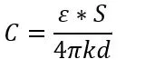
ε is the permittivity, S is the plate area, d is the plate separation, and 4πk is a constant.
Why MLCCs Achieve High Capacitance
To obtain large capacitance one can increase ε, increase S, or decrease d. In MLCCs the dielectric is ceramic, so ε is essentially fixed. Manufacturers therefore optimize S and d and use a stacked multilayer structure (see below):
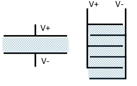
In a single flat-plate capacitor each electrode effectively uses only one face, so plate area is underutilized. The MLCC multilayer stack uses both faces of each internal electrode, effectively increasing the usable area; reducing plate spacing also raises capacitance, and adding more layers further increases total electrode area and capacitance.
Failure Mechanism
However, when plate spacing is reduced, the electric field E = U/d increases sharply for a given voltage increment. With very thin ceramic dielectric layers, a modest increase in voltage or a transient can significantly raise E and cause dielectric breakdown.
Therefore, high-capacitance MLCCs have relatively weak tolerance to voltage-breakdown fluctuations. Combined with manufacturing challenges in controlling uniform dielectric thickness, MLCCs are susceptible to breakdown under voltage transients, power-on surge events, or other voltage fluctuations.
Mitigation Strategies
- Choose larger MLCC package sizes for high-capacitance components where possible; larger internal spacing improves tolerance to voltage transients.
- Parallel multiple smaller-value, higher-voltage-rated MLCCs to achieve the required capacitance while increasing overall voltage margin.
- Where appropriate for the application, replace MLCCs with aluminum electrolytic or tantalum capacitors to avoid this specific thin-dielectric breakdown issue, recognizing those alternatives have different trade-offs.


