ALLPCB


Background
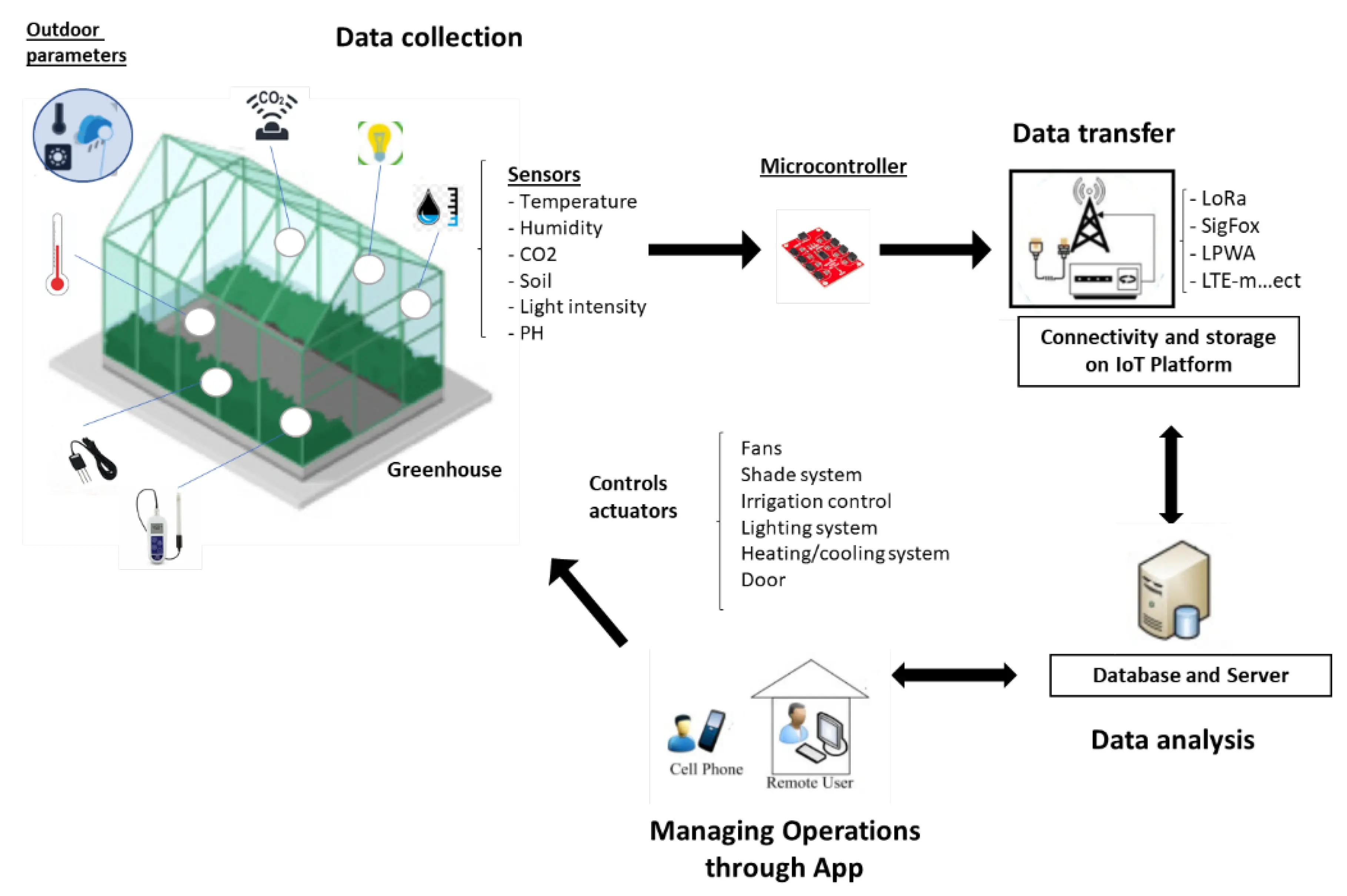
Temperature, humidity, and illumination are key parameters in agricultural cultivation. This design targets greenhouse cultivation and implements an IoT-based greenhouse alarm system using a Xinghuo-1 development board.
RT-Thread Studio is used for software engineering, configuration, and debugging.
The project was developed as a university embedded systems summer camp final assignment. Project members were students majoring in microelectronics, integrated circuits, and intelligent manufacturing.
Hardware Selection
Peripherals and sensor choices
The system uses the following peripherals and sensors:
- STM32F407 microcontroller: Acts as the main controller, responsible for system control and data processing. It provides sufficient processing power and a variety of peripheral interfaces.
- AHT10 temperature and humidity sensor: Measures temperature and humidity. It communicates with the STM32F407 via I2C to deliver the collected data to the main controller.
- AP3216 light sensor: Measures illumination intensity. It communicates with the STM32F407 via I2C to deliver light data to the main controller.
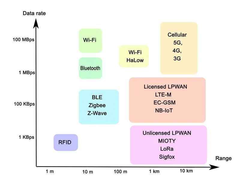
- RW007 Wi-Fi module: An SPI-interface Wi-Fi module that supports 802.11b/g/n for wireless data transmission.
Technical Functions
Thread data transfer
Data exchanged between threads includes:
- Temperature and humidity readings from the AHT10 sensor.
- Illumination readings from the BH1750 or AP3216 light sensor.
- Threshold values for temperature, humidity, and illumination used to determine alarm conditions.
- Alarm state flags indicating whether the buzzer should be triggered.
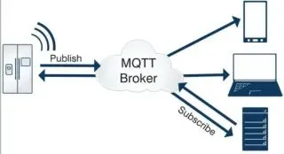
In the IoT greenhouse alarm system, the main controller thread receives sensor data and threshold values through shared memory or message queues. When uploading data to the cloud platform, a socket can be used for network transmission.
Synchronization is achieved using signals or mutexes to pass data to the alarm thread. The alarm thread evaluates the received data and controls the buzzer accordingly.
Program Operation Logic
Program execution steps:
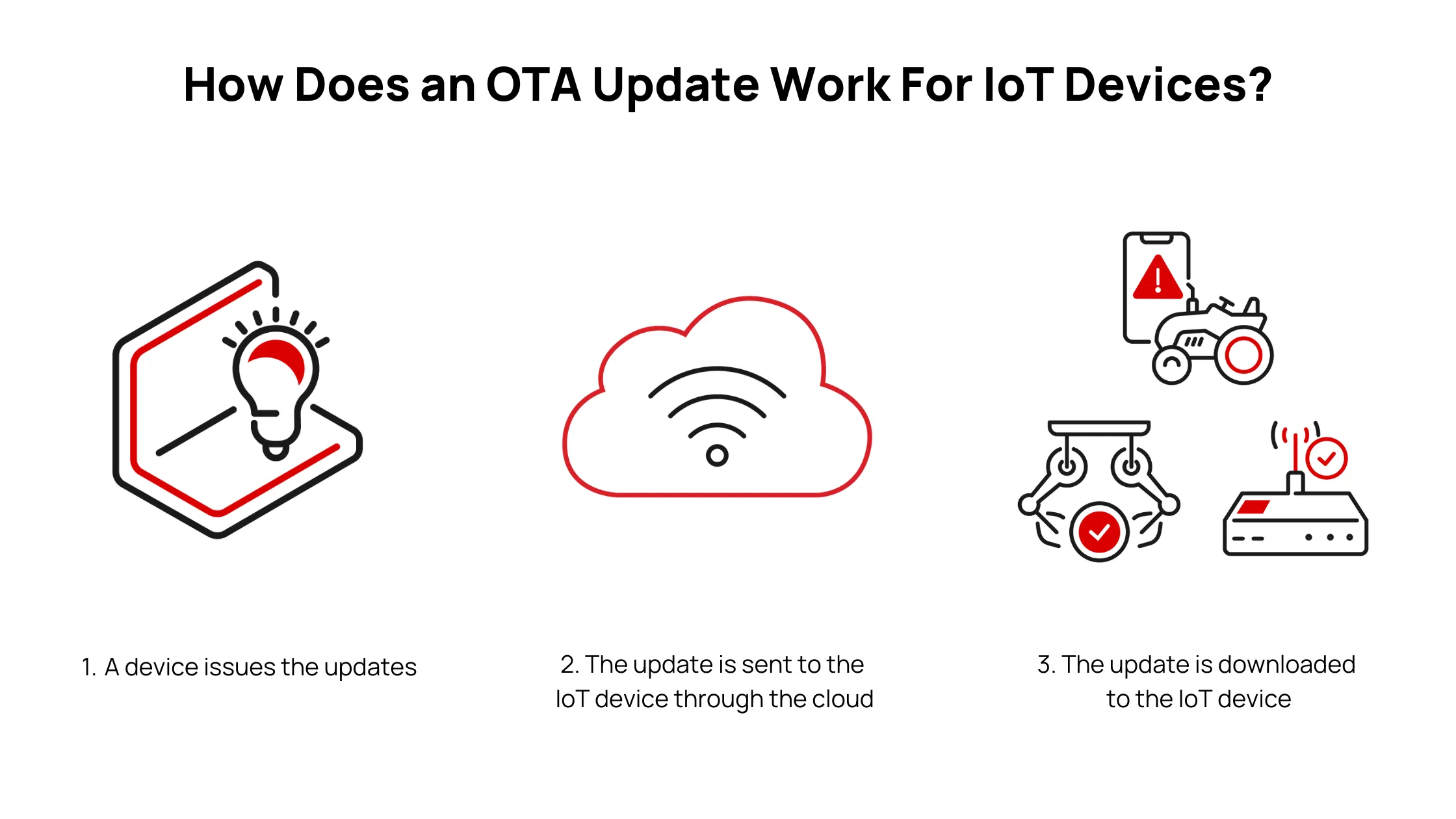
- The main controller thread reads sensor data and uploads it to the cloud platform via the network module.
- The cloud platform receives the data, performs analysis, and checks the preset thresholds to determine whether an alarm should be triggered.
- The cloud platform generates corresponding signals and sends them back to the main controller.
- The main controller thread receives the signals and controls the buzzer state based on the signals.
This approach enables remote monitoring and control. The main controller uploads sensor data to the cloud platform, which performs analysis and returns control signals to the controller to operate the buzzer, allowing more complex analysis and decision making on the cloud side.
Project Progress
Threads and synchronization
- rt_thread_1_entry: cloud platform alarm thread
- rt_thread1_entry: cloud platform alarm thread
- rt_thread2_entry: local command execution thread
- semaphore_sample: semaphore initialization
OneNet Analysis and Command Transmission
In the current implementation, OneNet is used to monitor and transmit data to the Xinghuo-1 board, which then performs local analysis and issues control commands. With further optimization, data analysis could be handled directly on the cloud platform.