 My Message
 Suggestions
 Account
Account
Account


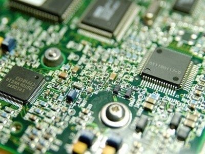
Category:PCB PCB Schematic
Schematic capture or schematic entry is a step in the design cycle of electronic design automation (EDA) at which the electronic diagram, or electronic schematic of the designed electronic circuit is created by a designer. This is done interactively with the help of a schematic capture tool also known as schematic editor.
Introduction In some of the technical articles, the converter operation is studied in ideal conditions. An ideal condition is when there is no interruptions, disturbances and errors that cause ...(view more)
A demonstration of filter inductor design for boost converters, design of the coupled inductor for a two-output forward converter, and the design of flyback transformer in continuous conduction mode. ...(view more)
Version 2.0 of the Pulsonix PCB design software suite boasts over 70 new features above the preceding version 1.2. Enhancements include true instanced multilevel hierarchy in schematics as well as ele...(view more)
I am having a lot of Diamond symbols in my schematic. I am not able to find the means of them. Are there any general conventions that govern the usage of symbols in schematics? (view more)
Can anyone suggest a good schematic capture checklist to use? I'm using DX Designer, so if you have specific checks you run, let me know about that too. (view more)
There are one large schematic with 3 separate PCBs that I need to have assembled. What is the best approach to output a BOM for each PCB? The size of PCB is 3.5" x 6.5" each. And I use EagleCAD 6.6. ...(view more)
Can you give me recommendations for a schematic drafting package?(view more)
I am working on a bipolar power supply for hobby and educational purposes. Concerning the schematic, is it possible to place devices that don't go on the PCB in the schematic?(view more)
I have the current schematic with a full line of capacitor which I suppose are by pass capacitor. The schematic show a unique point of connection on the 56 pin however I suppose that each capaci...(view more)
I want to create a second, alternate PCB from the same schematic. This board will be electrically the same, but use different parts packages and have a smaller overall size. Is it possible?(view more)


Please send Gerbers to service@ALLPCB.com for quotation © ALLPCB.com,All Rights Reserved Privacy PolicySitemap


