 My Message
 Suggestions
 Account
Account
Account


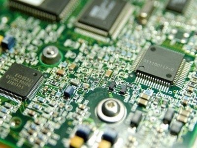
Category:PCB PCB Design Rules
Initially PCBs were designed manually by creating a photomask on a clear mylar sheet, usually at two or four times the true size. Starting from the schematic diagram the component pin pads were laid out on the mylar and then traces were routed to connect the pads. If you have many questions of PCB Design, please come here!
I can center the grid to a pad in 2013 veresion of RC. Is it possible in 4.0?(view more)
I am designing high-speed TTL-based processor. I will be using fast AC, ACT and LVC series, so switching frequencies will be in 100Mhz range with 1-3ns fronts. I plan to use double-sided PCB, Bo...(view more)
I'd like to know best way to make traces on universal PCB's with individual holes.(view more)
I've fond that every single modern PCB is routed at 45 degree angle increments. Why does the industry prefer this so much? Doesn't any-angle routing works better?(view more)
How to toggle visibility of the GND airwires in the ratsnest?(view more)
There is a PCB design with 3 SIM800 GSM modules sharing a external antenna. The external antenna is connected to the PCB via an antenna connector, and from that connector, the antenna signal is “sh...(view more)
I try to add a via in Cadstar and I think I can add a via with the add a via command manually. But I failed. What should I do?(view more)
Although the lines leaving the IC in the middle start fairly close to each other, they are significantly separated through the edge of the PCB. The width of and spacing between the leaving lines are ...(view more)
I changed pad net name in PCBnew, but the change reverted when I reload the netlist. Is there a way to lock the changed name so that they will not reverse?(view more)
The lectrolyte capacitor hole diameter is 0.6mm, what the drill hole size and pad outer size should I decide?(view more)


Please send Gerbers to service@ALLPCB.com for quotation © ALLPCB.com,All Rights Reserved Privacy PolicySitemap


