 My Message
 Suggestions


The expansion board of Arduino is called Shield, while raspberry pi expansion board is named as HAT (Hardware Attached on Top), referring to the hardware board attached to the top of raspberry pi. Now let’s design an open source raspberry pi expansion board, temporarily named Raspberry Pi ICA HAT.

1. Demand analysis
HAT is designed to provide raspberry pi with basic display and user input function, and leads to hardware interfaces such as UART, I2C, SPI, etc. It easily accesses to other modules and serves as the starter board for users who learn the raspberry hardware. The ICA HAT is configured as follows:
1. Key x5 can be used as the button of up, down, left, right and “OK";
2. User LED x4 is to achieve the basic instructions, and another LED is for power indicator;
3. Active buzzer x1, providing alarm function;
4. Infrared emission tube x2, infrared receiver head x1, to achieve infrared remote control function;
5. Seven-segment digital tube x2, to achieve 8-bit digital display, through the MAX7219 chip driver of SPI interface;
6. Several I/O and power extension pin.
After setting the demand, you should consider the structure firstly. This case is designed for the raspberry pie 2B model, but also compatible with the generation of B+ models. The following picture shows the mechanical structure of raspberry pie 2B/B +:

For the mechanical structure of raspberry pi, you can design two HATS of full and half length. The frame size of full-length board is the same as the raspberry pi. Considering the raspberry pi USB and RJ45 connectors are high, you should check whether the devices at the bottom will touch the connectors.
The half-length board contains only four screw holes.
Both boards are connected to the pins on the main board by 2.54mm spacing and are secured to the motherboard via four M2.5 copper studs or screws. As shown below:


Storing two HATs in the GitHub, then the reader can begin design.
After analyzing the mechanical structure, you should consider the I/O resource allocation. In 2B/B+ of raspberry pi, I/O includes two SPI interfaces, two I2C interfaces and one UART interface, except for the hardware of PWM and ADC. Additionally, I2C0 is used to read HAT board information as IDPROM interface, but the users can not use. SPI1 is also known as SPI_AUX in the CPU, the current Linux driver can be invoked by the pigpo library though it is not perfect currently. As shown below:

In this example, SPI0, I2C1 and UART0 are led out to the pins; SPI1 is used for controlling by MAX7219 and GPIO are allocated arbitrarily according to the wiring.
2. Hardware design and production
After demand analysis, then we come to the hardware design. Taking Cadence 16.6 tools for example, schematic tool is OrCAD Capture CIS, and Allegro PCB Editor is for PCB tool.

For the IDPROM, you should connect an EEPROM and raspberry piI2C0 firstly. This part of the circuit is not installed in the actual production for reserving function (the actual non-welding device is defined as NC).The user LED is controlled by the GPIO current and the LED lights when IO is low.

The key function is achieved by the GPIO detecting the electrical level on left side. The level is high when the key is released and low after pressing.

Infrared tube needs a large current, so a GPIO is required to drive the infrared LED by controlling NPN transistor, and the infrared tube will be conducted on high electrical level. Of course, you can only weld and use one LED, and two LED can enhance the infrared signal.

Integrated receiver HS0038 is used for receiving infrared, which can work at 3.3V voltage and receive infrared signals via a GPIO.

Active buzzer also requires a large current, just like infrared tube, it is driven by transistor and the buzzer sound when GPIO reaches high electrical level.

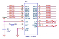
Digital display is using two 4-bit 7-segment digital tubes (common cathode, count the decimal point is actually 8), and is driven through the MAX7219 chip. MAX7219 offers display up to 8-segment and 8-bit, where the MAX7219 segment A-DP is connected with two digital tube in order simultaneously, for displaying the contents of each bit. And selection signals of MAX7219 digital are connected to the each common port of two digital tubes.
The MAX7219 is connected to the raspberry by SPI, and DOUT is not necessary to connect as it only needs control instead of reading information. Chip is power supply by 5V, strictly speaking, the SPI should use the 5V. 3.3V electrical level can also be normally controlled through raspberry pi, but it is recommended to set the electriclevel conversion circuit.

As for the interface expansion pin, the series of 100ohm resistance plays the role of current limiting protection. Each interface respectively provides 3.3V power and GND.


ICA HAT PCB is using low-cost double-sided boards (only 50RMB for 10 PCB productions) and the layout should be explained.
According to the general users habits, the digital tube placed in the upper part of the board side by side (the most eye-catching position), the keys on the lower right corner of the board (left-hand friends can place on the left). Infrared transceiver and IO interface are neatly arranged around the board edge to prevent blocking for easy wiring. Besides, LEDs and buzzers can be placed in the middle of the board.


Designed PCB files can be exported to Artwork and Drill files submitting to PCB manufacturers. Domestic manufacturers typically receive Altium Designer and Protel format engineering documents which actually are converted to Artwork for manufacturing. Manufacturers will also provide free testing to ensure that the circuit does not appear short circuit, etc. Here is the picture showing good PCB:


The component soldering is after PCB production, and it is necessary to provide a solder mask file for the stencil production and assembly file if soldered by machines.
Since the component is simple and small, we can manually weld from the difficult and pin-intensive (SMD) IC, then the components of the lower height, and finally higher through-hole parts. The connector and the digital tube can be welded in the end. The following figure shows the manual completion of circuit board, namely, PCBA:


It should test the circuit whether short circuit exists after the welding, especially in the power supply. Only after that can you use electrical test, otherwise it may not only burn the HAT board, but damage the main board of raspberry pi.


Eduardo Gonzalez
2017/4/10 15:47:28
It seems a bit complex, but I will try if get time.
henrik.svensk
2017/2/26 16:20:59
Really appreciate your content.I hope you write again soon.